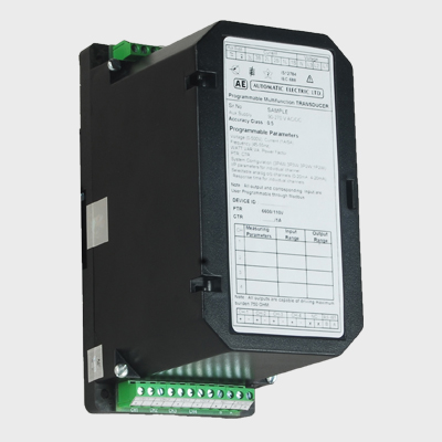
PROGRAMMABLE MULTIFUNCTION TRANSDUCER (PMT-9)

Description :

The PMT-9 Multifunction Programmable Transducer measures the several variables of an electric power system and processes them to produce 4 analog output signals. 2 digital output signals are available for signaling the limits. The limits of the outputs can be set by individual measurand or logically combine up to three measurand. The principle of measuring is Dedicated DSP Controller for best calculation of RMS values and Power.

The PMT-9 is equipped with USB serial port interface through which using the corresponding software one can connect, program, or access and execute useful ancillary functions. The ancillary functions include a power system check, provision for displaying the measured variably on a PC monitor, the simulation of the outputs for test purposes.

The PMT-9 is also equipped with a RS 485 bus interface (MODBUS®). The RS 485 interface enables the user to determine the number of variables to be supervised (up to the maximum available). The levels of all internal power/ energy meters that have been configured can also be viewed. Provision is made for programming the PMT-9 via the bus. A standard EIA 485 interface can be used, but there is no dummy

Features :

Simultaneous measurement of several variables of a heavy-current power system / Full supervision of an asymmetrically loaded four wire power system, rated current 1 to 6 A, rated voltage 57 to 400V (phase-to-n€ utral) or 100 to 693 V (phase-to-phase)For all heavy-current power system variables.

  • Fully Programmable CT and PT Ratio.
  • 4 analogue outputs
  • Digital Outputs
  • Conversion of a current to a voltage output or vice versa is also possible without any hardware change.
  • Input voltage up to 693 V (phase-to-phase)
  • Universal analogue outputs (programmable)
  • High accuracy: U/I 0.2% and P 0.25% (under reference conditions)
  • Windows software with password protection for programming, data analysis, power system status simulation, acquisition of meter data and making settings

Applicable Standards :

EN 60688(2012) :Electrical measuring transducers for converting AC electrical variables into analog and digital signals

IS 12784:Electrical measuring transducers for converting ac Electrical Quantities into dc Electrical quantities – specification.

IEC 1010 or EN 61010:Safety regulations for electrical measuring, control and laboratory equipment

IEC 61326 – 1 :Electromagnetic compatibility for Electrical Equipment for measurement, control and

Technical Data :

Inputs

Input variables :U,U1N,U2N,U3N,U12,U23,U31,UM, 1,11,12,13,1M,IMS,P,P1,P2,P3,Q,Q1,02,03,S,S1,S2,S3, PF,PF1,PF2,PF3,0F,QF1,0F2,0F3,LF,LF1,LF2,LF3

Symbols Meaning :

  • X:Measured variable
  • XO:Lower limit of the measured variable
  • X1:Break point of the measured variable
  • X2:Upper limit of the measured variable
  • Y:Output variable
  • YO:Lower limit of the output variable
  • Y1:Break point of the output variable
  • Y2:Upper limit of the output variable
  • U: Input voltage
  • Ur:Rated value of the input voltage
  • U12:Phase-to-phase voltage L1 — L2
  • U23:Phase-to-phase voltage L2 — L3
  • U31:Phase-to-phase voltage L3 — L1
  • U1N:Phase-to-neutral voltage L1 — N
  • U2N:Phase-to-neutral voltage L2 — N
  • U3N:Phase-to-neutral voltage L3 — N
  • UM:Average value of the voltages(U1 N+U2N+U3N) / 3
  • I :Input current
  • I1:AC current L1
  • I2:AC current L2
  • I3:AC current L3
  • Ir:Rated value of the input currentI
  • IM:Average value of the currents (11 + 12 + 13) / 3
  • IMS:Average value of the currents and sign of the active power (P)
  • ø:Phase-shift between current and voltage
  • F:Frequency of the input variable
  • Fn:Rated frequency
  • P:Active power of the system P = P1 + P2 + P3
  • P1:Active power phase 1 (phase-to-neutral L1 — N)
  • P2:Active power phase 2 (phase-to-neutral L2 — N)
  • P3:Active power phase 3 (phase-to-neutral L3 — N)
  • Q:Reactive power of the system Q = Q1 + Q2 + Q3
  • Q1:Reactive power phase 1 (phase-to-neutral L1 — N)


  • 02:Reactive power phase 2 (phase-to-neutral L2 — N)
  • Q3:Reactive power phase 3 (phase-to-neutral L3 — N)
  • S:Apparent power of the system ;
  • S=√(I1 + I2 + I3)+√(V1 + V2 + V3)
  • S1:Apparent power phase 1 (phase-to-neutral L1 — N)
  • S2:Apparent power phase 2 (phase-to-neutral L2 — N)
  • S3 :Apparent power phase 3 (phase-to-neutral L3 — N)
  • Sr:Rated value of the apparent power of the system
  • PF:Active power factor cos ɸ= P/S
  • PF 1:Active power factor phase 1 cos ɸ1 = P 1/S 1
  • PF2:Active power factor phase 2 cos ɸ2 = P2/S2
  • PF3:Active power factor phase 3 cos ɸ3 = P3/S3
  • QF:Reactive power factor sin ɸ = Q/S
  • QF 1:Reactive power factor phase 1 sin ɸ1= 01/S1
  • QF2:Reactive power factor phase 2 sin ɸ 2= Q2/S2
  • QF3:Reactive power factor phase 3 sin ɸ 3= Q3/S3
  • LF:Power factor of the system LF = sgnQ • (1 — 1-PF1)
  • LF 1:Power factor phase 1 LF1 = sgnQ1 • (1 — 1-PF1)
  • LF2:Power factor phase 2 LF2 = sgnQ2 • (1 — 1-PF1)
  • LF3:Power factor phase 3 LF3 = sgnQ3 • (1 — 1-PFI)
  • c:Factor for the intrinsic error
  • R:Output load
  • Rn:Rated burden
  • H:Power supply
  • Hn:Rated value of the power supply
  • CT:c.t. ratio
  • VT:v.t. ratio


Measuring Ranges :

id_pg54_tbl1
id_pg54_tbl2

Output :

programmable-multifunction-fig-3

4 analog outputs following the corresponding process variable programmed through the software. These signals can be set in various patterns like Linear, live zero, bent. The outputs A, B, C and D may be either short or open-circuited. They are electrically insulated from each other and from all other circuits (floating). All the full-scale output values can be reduced subsequently using the programming software, subjective a supplementary error results. Conversion of a current to a voltage output or vice versa is also possible without any hardware change.

id_pg54_tbl3
programmable-multifunction-fig-4
id_pg55_tbl

Electrical Connections :

Environmental :

  • Weight:408 gm.
  • Vibration / Shock:12 g, 10-55-10 Hz
  • Relative Humidity :0 to 95% non condensing
  • Storage:-10 to +70 deg c
  • Working Temperature :-5° to +55° C

Safety :

  • Protection Class:Class II
  • IP Rating:IP20
  • Over Voltage Cat :Cat III
  • Insulation Test Vs Earth:500V
  • Surge Test:5KV, 12/50us, 5WS
  • HV Test:Up to 0/p isolation 4KV
  • o/p to o/p isolation 500 V 2KV Communication Interface
  • (USB / RS485) to all circuit 2KV
programmable-multifunction-fig-2